This webpage will describe at a high level how I made a DC lab-bench power supply. I have written this account to serve as a how-to tutorial so others can replicate my methods and designs. It is important to note that there are many ways to get to a similar end result. A different enclosure, front panel, cable jacks, power switches, boost/ buck converter and or ATX power supply can easily be swapped with similar components to meet your needs.
If you intend to follow this as a how-to, I highly recommended you skim through this guide prior to beginning the project. This is intended to be a challenging build; moderate woodworking and electronics skills will be helpful. If you are inexperienced, this manual will be a great way to learn. Although it may be overkill, a dual channel variable DC lab bench power supply with 4 constant potential outputs and multimeter such as the one described in this manual has became one of my favorite tools. Here is an overview of my design’s functionality:
There are many things to consider when building your own tools. Higher-end consumer power supplies have variable negative and positive direct current channels plus a ground. A digital volt and current meter is a necessary component. I will be building one with those features plus a constant +12, +5, +3 and -12 volt channels. Those values are standard supply voltages for digital circuits. Having 6 channels gives the operator freedom to test many isolated circuits.
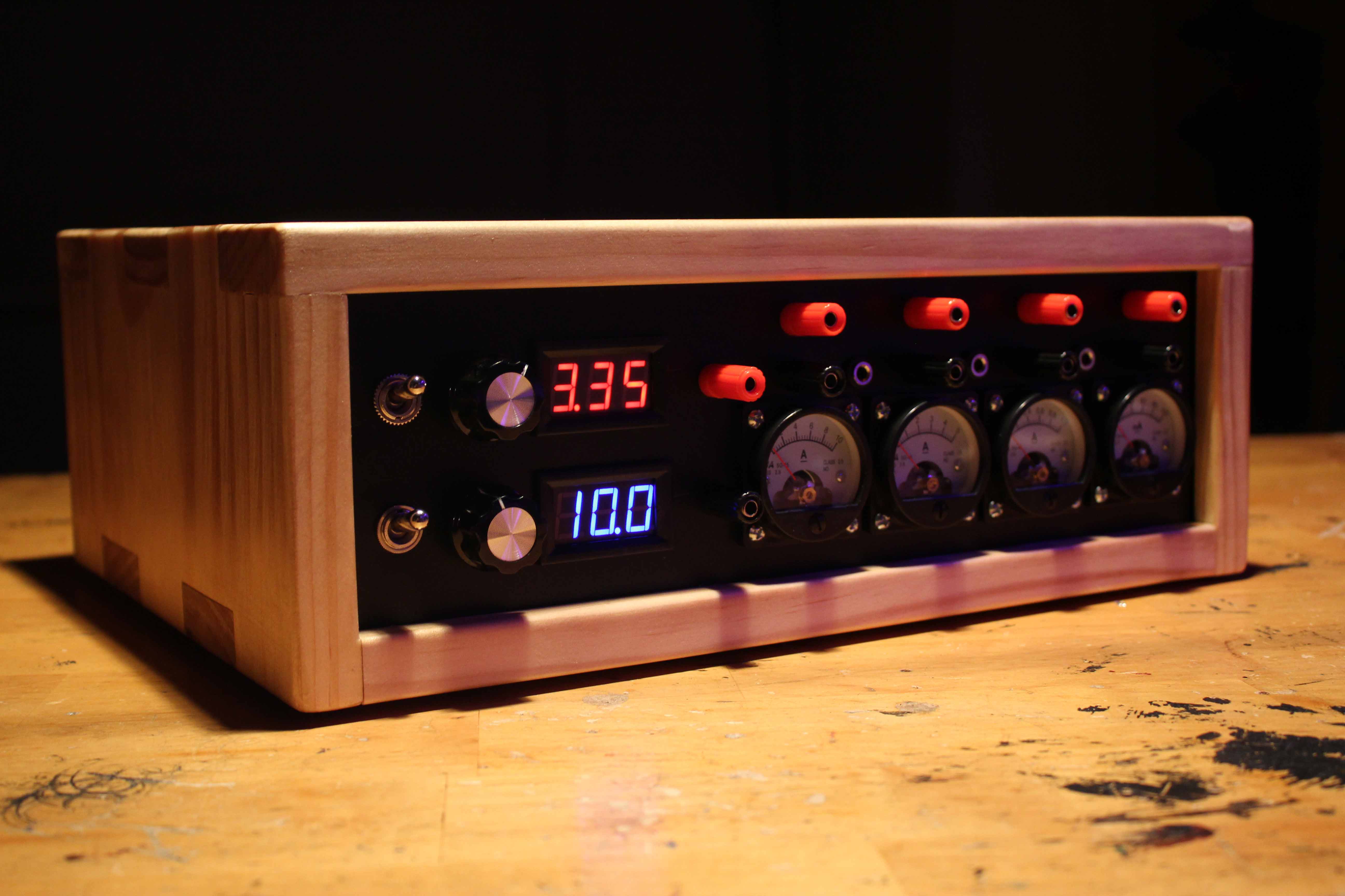
Since a power supply is often at the center of a workbench, it is wise to make it attractive. The volt, current meters and panel is where careful thought is focused. Amazon, Ebay, and many other ecommerce sites have a wide selection of components. This manual describes how to make a device with round analog current meters, and 7-segment LED volt meters.
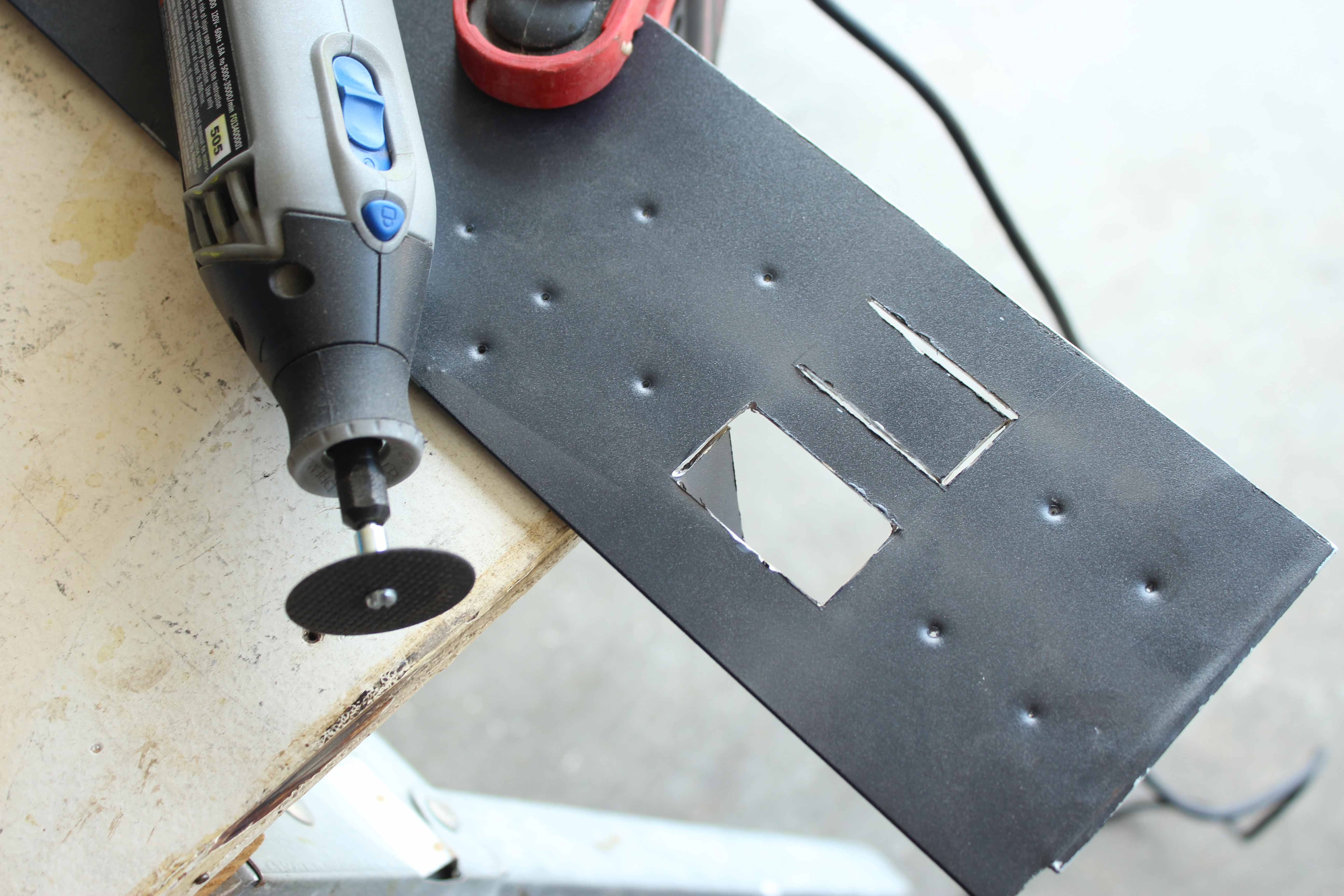
I would like to offer some advice before you choose components. I found it extremely difficult to cut the rectangular holes for the volt-meters with a Dremel. The cut-off wheel tended to kickback and left marks on the metal that show through the paint. Another consideration is the hole bits for the current meters. I initially tried to use a hole bit designed for wood. I completely ruined the bit before making a single hole. A 1-1/4" hole bit for cutting metal will set you back $50. My recommendation is to just get the panel plasma cut through Etsy.com. If you are dead set on cutting it manually, consider an acrylic sheet, but be mindful of the thickness and the components you plan to mount.
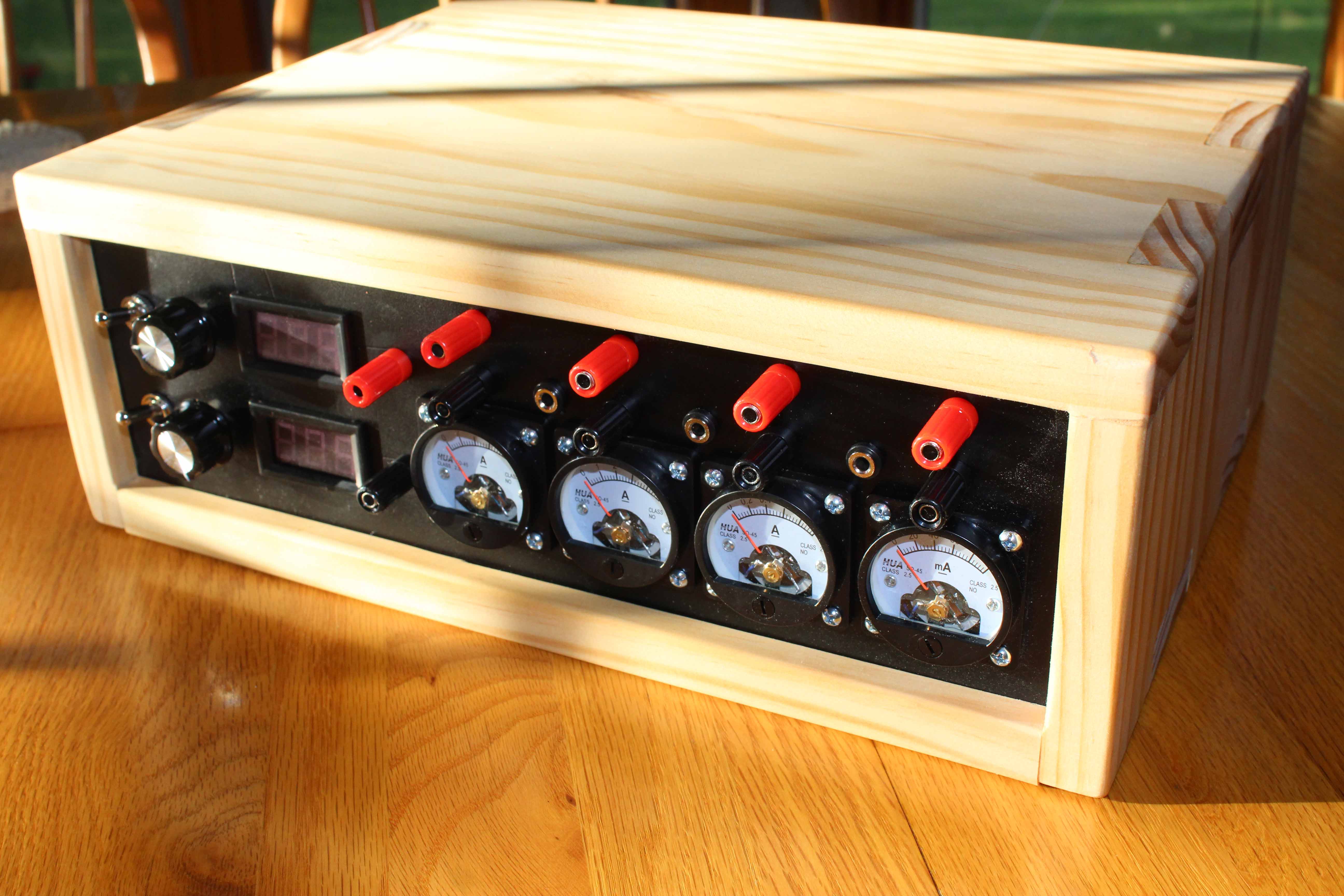
The only rules for an enclosure is that the power source(s), boost/ buck converters, and cabling must fit neatly inside with the control panel in the front and still without being to large to sit on one’s work station. This design is made with the intent to set a 17” laptop on top for programming microcontrollers and reading datasheets. Plastic enclosures can be purchased online, or reused from debunked consumer devices. This one will be made from pine in order match my other creations. Don’t forget to include some sort of ventilation so the PCBs don’t overheat during high power consumption.
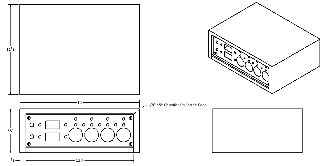
Electrical and mechincal schematics can be found here.
Using an angle grinder with cut-off wheel, cut your front panel to size. Error on the larger side and account for an extra ⅛” on each side for insertion grouves. Do the same for the rear panel. Safety: Always wear eye, ear and lung protection when using an angle grinder.
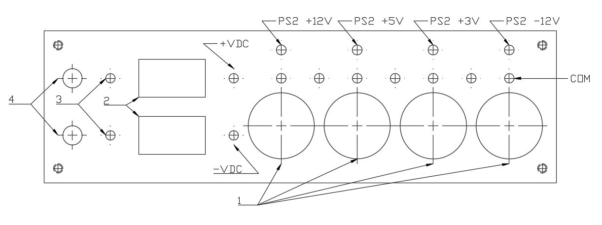
Either tape a to-scale layout drawing to your material, or use a square, pencil and ruler to find the center location for each component. Use a hammer and nail set to mark each center in order to prevent drifting of the drill bit. For straight cuts, use a sharp knife to scratch lines into the material.
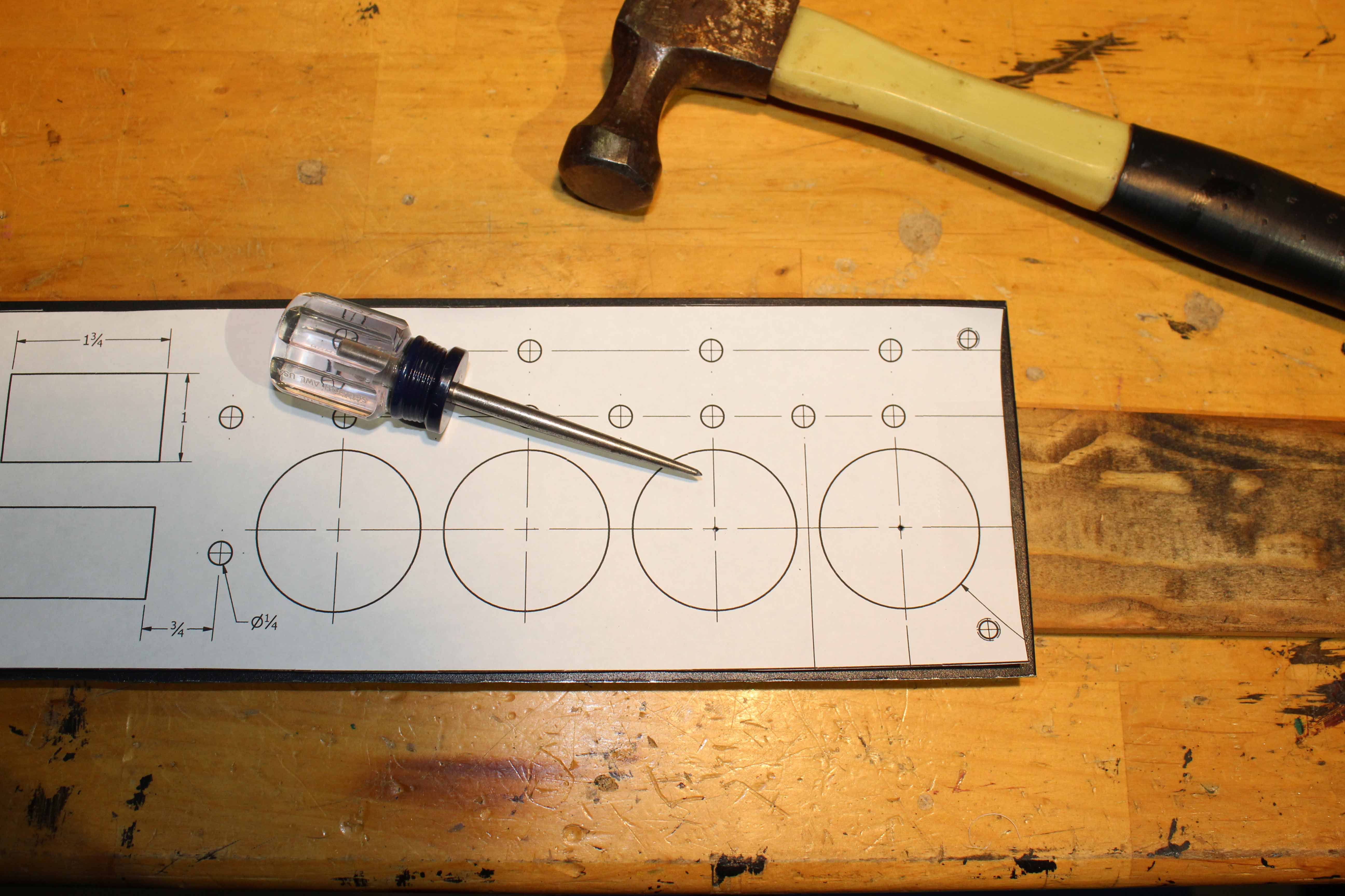
A dremel tool with a metal cut off wheel is used to cut square holes, and drill bits for circular. I used a 5/16” bit for the panel jacks, 1¾” for current meters and ⅜” for potentiometers and power switches. It is criticly important to place clamps as near to each hole you drill. This prevents the bit catching the metal and warping it. If you have access to CAD software, custom CNC plasma cutting is available online. This route is highly recommended if you are able to wait for the panel to ship.
Use a half-round metal file to remove any sharp edges and burrs from the front and back panels. Lightly go over the panels with 100 grit sandpaper to prepare it for paint. Remove any dust or debris. Any old can of spray paint rated for metal adhesion will work for the panels. Follow the directions included on the can. Do this step outdoors, applying several coats as you see fit.
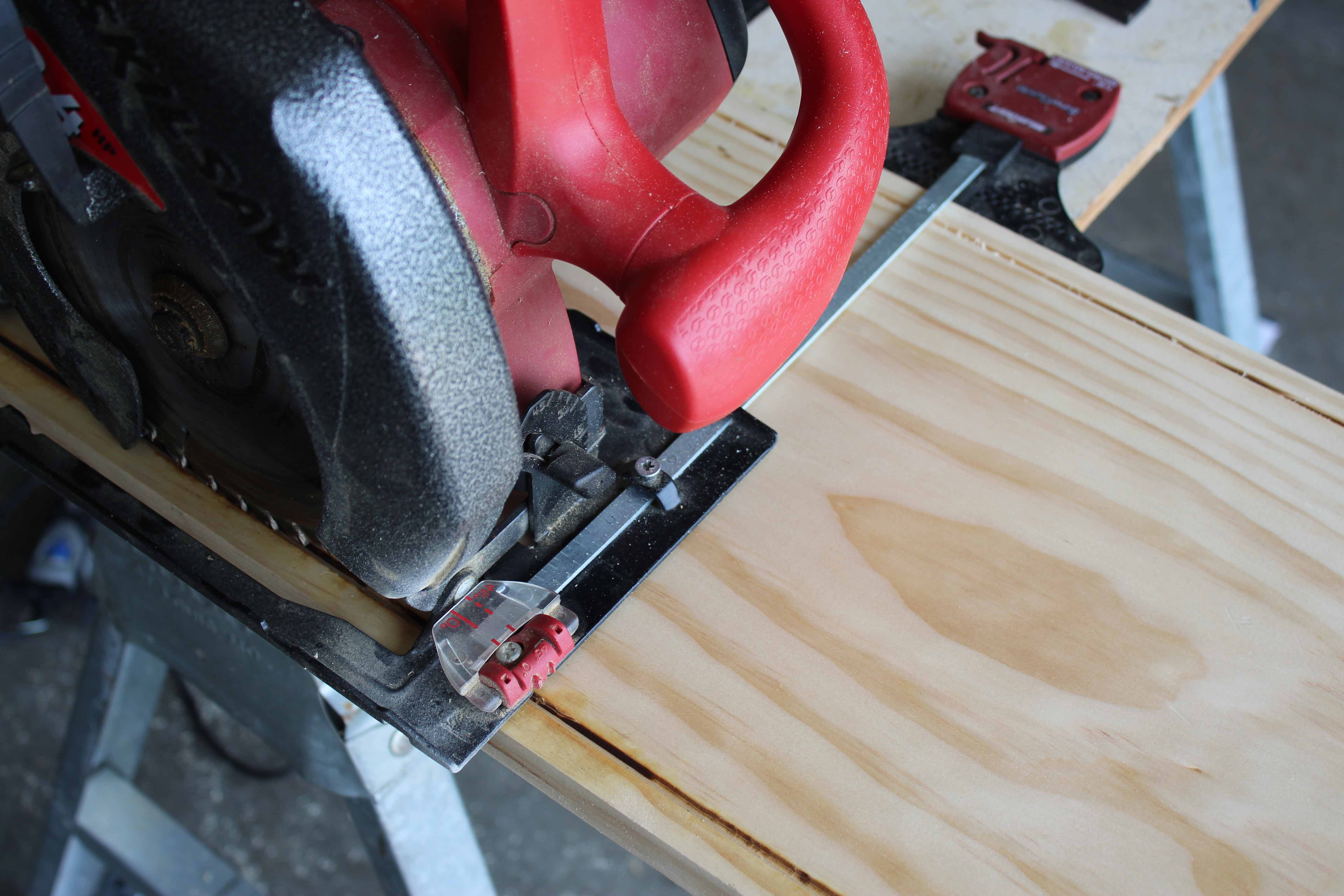
Using a circular saw and edge guide, create a slot for the front and rear panel to sit. Set the edge guide to ½” and blade depth to ⅛”. Pick your favorite 4-foot section on the 1”x12”x8’ board and remove material ½” in from either side on one face. The face that now has the 2 parallel grooves will be the inside. If you have access to a table saw, absolutly use that instead.
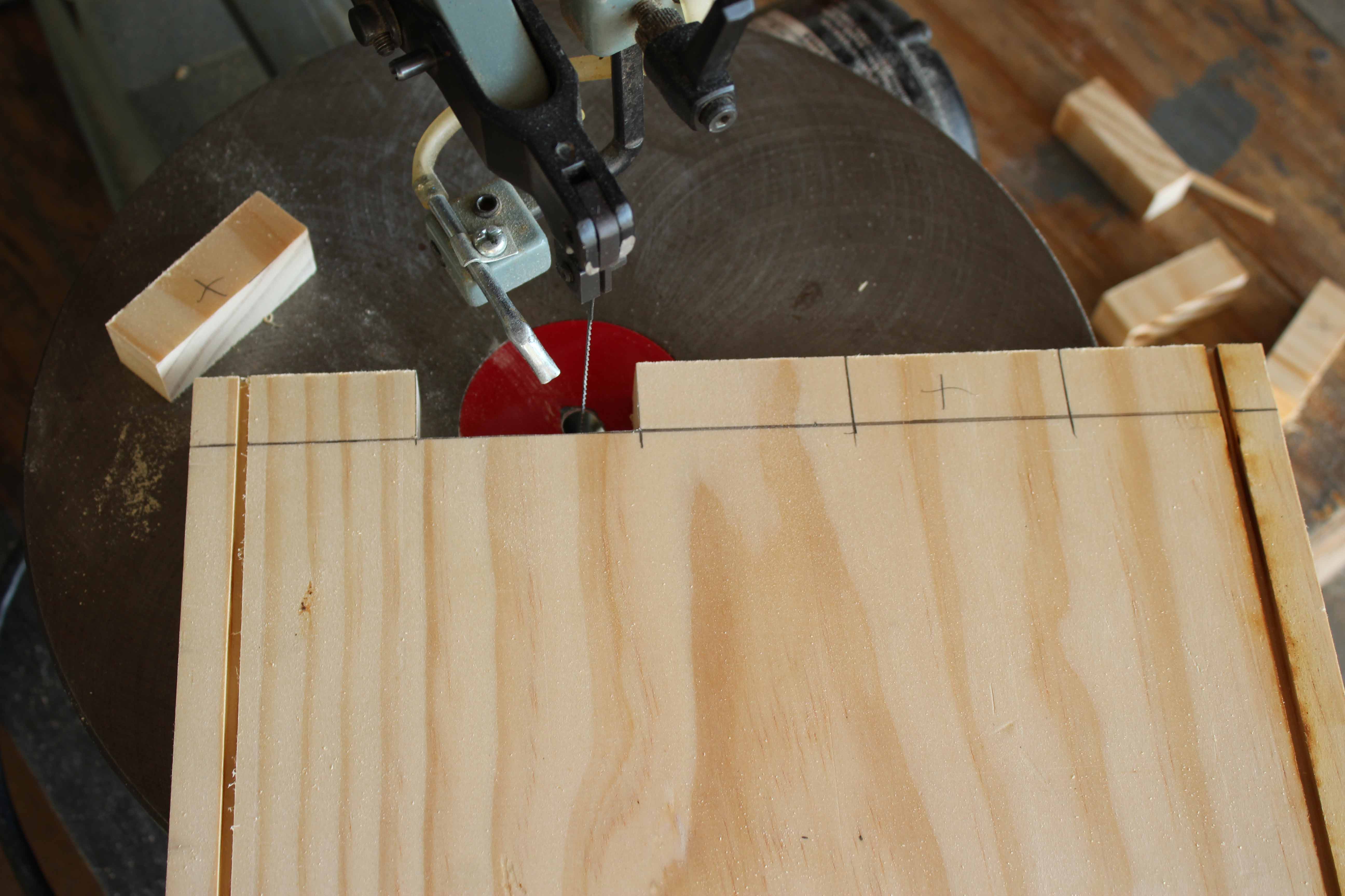
Using a miter saw, I cut two 15”, and two 5½” long sections from the 1”x12” grooved board. On the end of each section make a mark every 2¼”. Trace the depth of an extra piece of material onto the face of the marked ones. Use a square to make 5 rectangles from the marks as shown in the photo. I cut the box joints on a scroll saw for the top, side and bottom panels. However, if you have access to a router or table saw, I HIGHLY recommend making the joints on that. The scroll saw does not cut straight lines well, and is not nearly precise enough for fine joinery. Either way, error on the deeper and thinner side for each finger. Be careful to cut the correct patterns so that each piece fits together correctly.
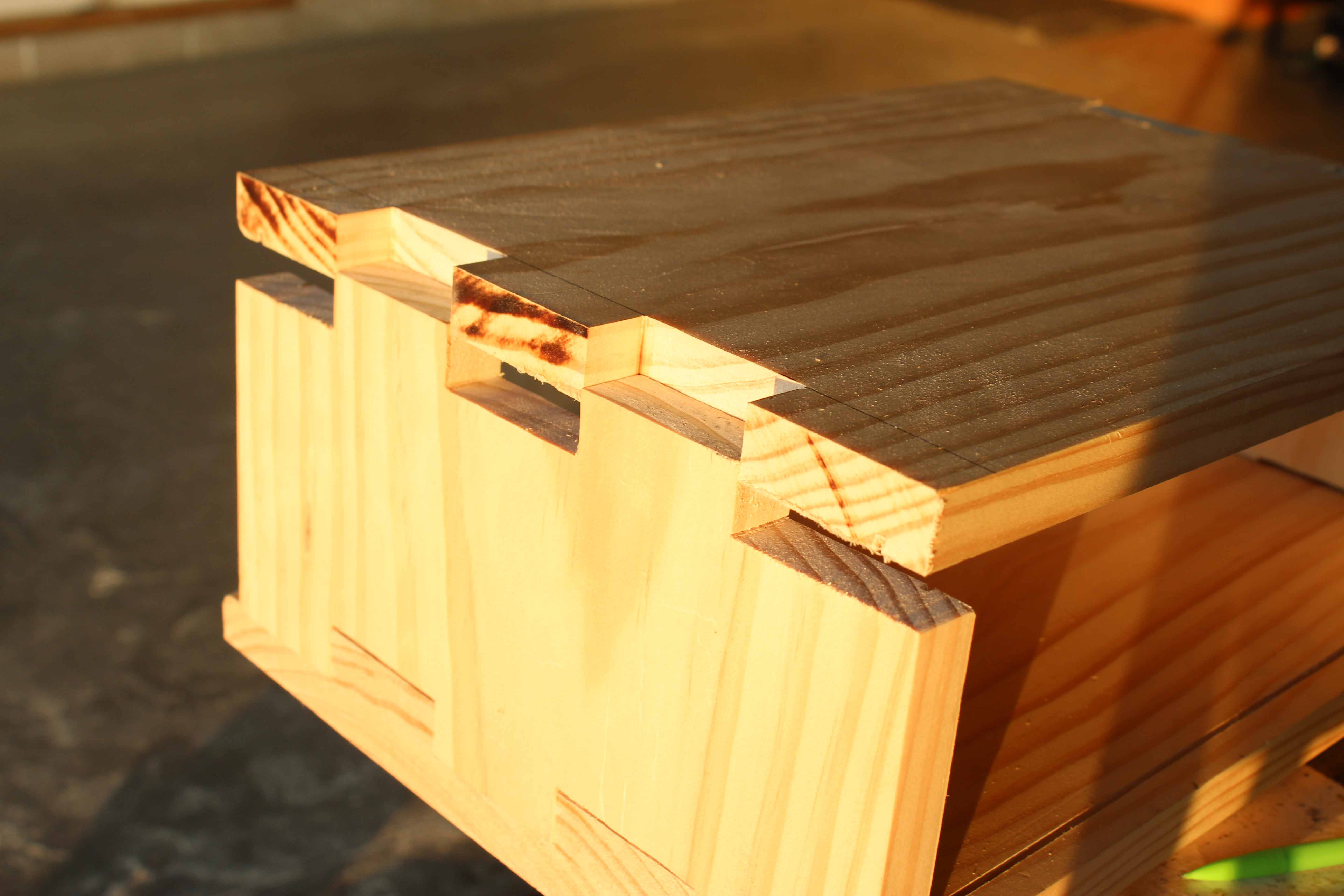
Start by perfecting box joints using a course file. Glue together the top and sides only. Drill pilot holes to attach the bottom to the left and right sides with wood screws. Do not use glue on the bottom so that the front panel can be inserted into the groove. If you would like, use a chamfer bit on a router to add a decorative edge to the piece. I used a power-sander held at a 45 degree angle which makes a surprisingly nice 1/16” chamfer without chipping the end-grain. Troubleshooting gaps: mend with wood filler and let dry before sanding.
Once the enclosure is glued and screwed, give it a good sanding to a fine grit starting with 80. Remove any nics, saw burns, and sharp edges. This step should be done before installing any electrical components including the front and rear panel. Next, using an old piece of white fabric, dip it in wood stain and lather it on to the enclosure. Once you cover the entire piece, use a clean fabric to wipe off excess stain. Let it dry overnight in a well ventilated area. I used Minwax Natural stain which really dosn’t do much for the color but brings out the wood grain. If you want to just skip right to polyurethane, you probably won’t even notice a difference.
With the enclosure still assembled minus the panels and electronics, you can apply Polyurethane to the project. Use a paint brush to apply two light coats letting it dry for 24 hours in between. Start with the top and sides, let it dry, then do the bottom and inside.
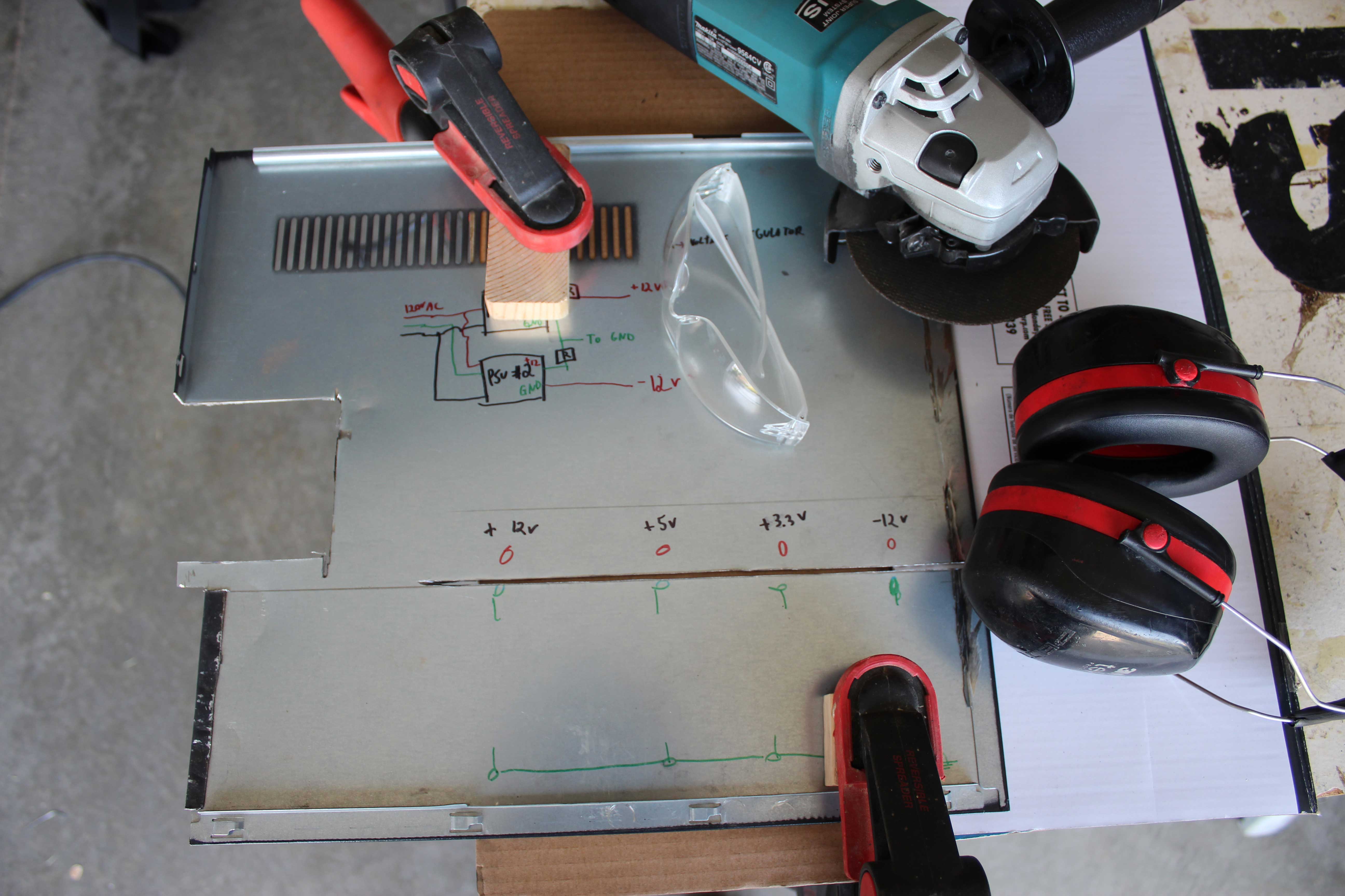
As you work, be sure to follow the wiring schematic noting any changes made. Having an accurate schematic with wire labels, colors, and descriptions will save time in the long run when debugging your system. Work with the enclosure up-side-down, without the bottom. Have the front and rear panel in place. 4.1 Power
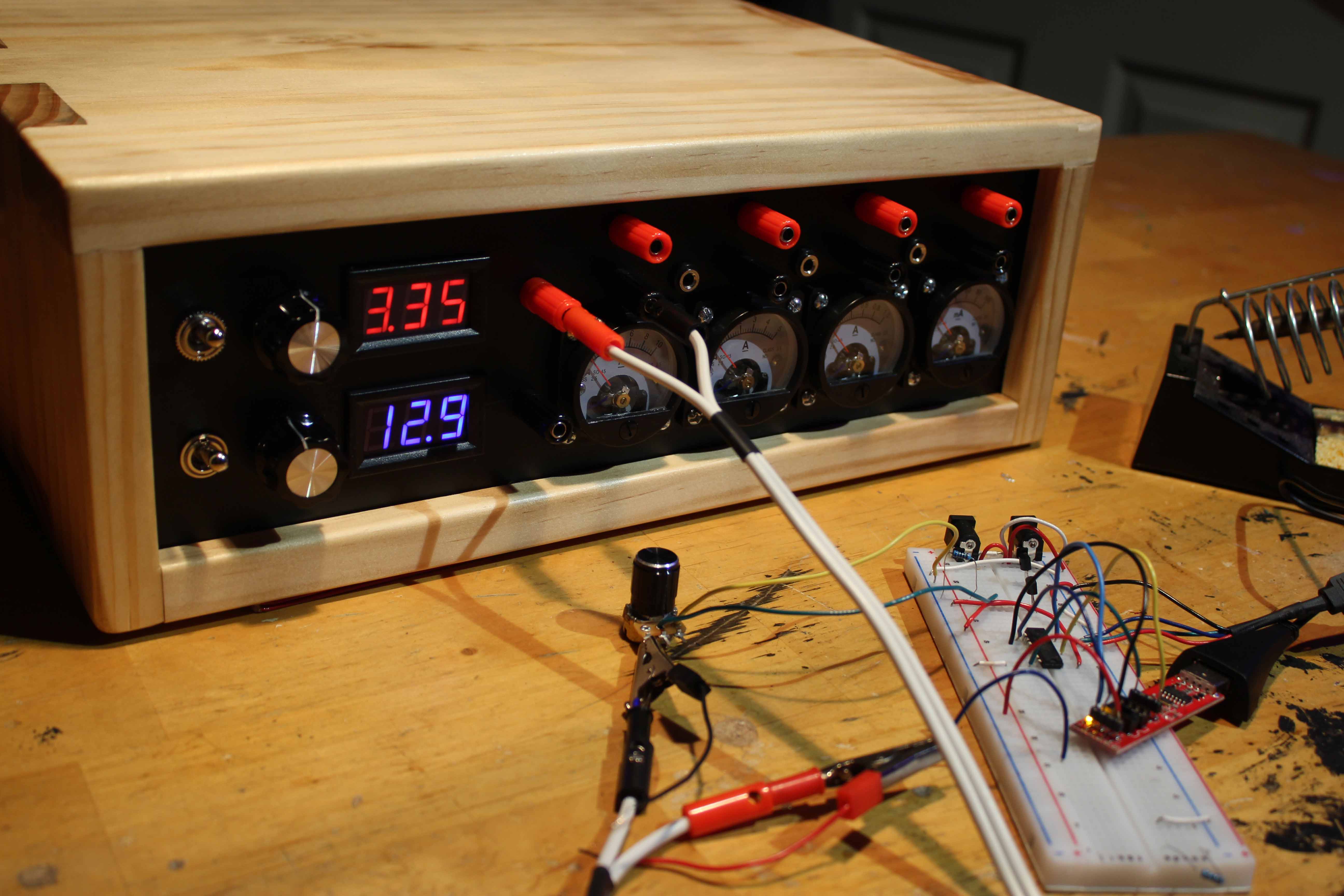
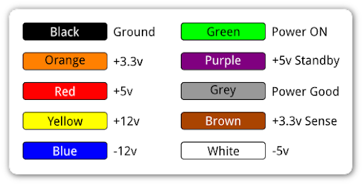
Start with the ATX power sources. Cut the cables just short of the existing connectors. For the supplies to turn on, you must short the green wires for both sources to their respective black wire. Next, on the second source, remove the ground from the AC input. This allows you to create an “apparent ground” on the load side from the boost/ buck converter off of source 1. From here, follow the attached wire schematic, checking, double checking, and highlighting new connections as you go. Soldering wires to devices is the most permanent, but using a crimp set will work fine too.
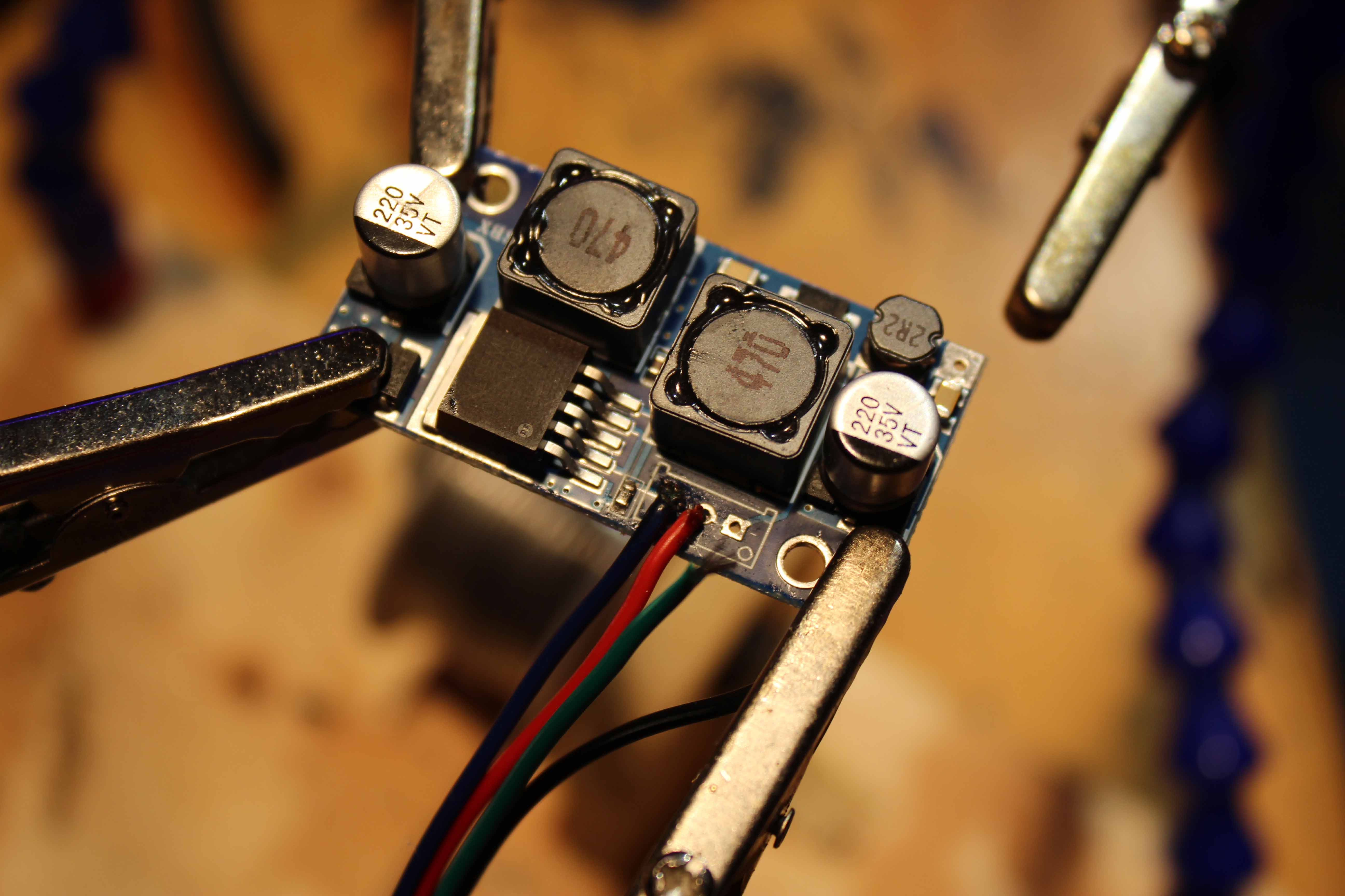
In order to have variable voltage levels, you must remove the existing potentiometer from the boost/ buck converter and relocate a panel mount version to the front panel. It is crucial that the new and factory potentiometers have the same resistance other wise you will destroy the boost/ buck. Wire the new potentiometer to the boost/ buck in the exact configuration as the old one. Make sure the voltage output increases when the potentiometer turns clockwise. If it does not, reverse pins 1 and 3.
Start by attaching each component to the front panel. Once you have determined they all fit properly, continue following the electrical schematic. CAUTION: Wires are easily shorted to a metal panel rendering the system defective.
After all the components have been wired and tested, mount them on the inside of the enclosure. It is wise to attach components so that there is plenty of air flow on all sides. Ensure that the rear and front panels fit snug inside the top and sides of the enclosure before reattaching the bottom. Use wood screws to secure the sides to the bottom. Now test it out and build some circuits!