Prior to implementing a CAD model, several basic design choices were considered. Functionality was the primary concern of this project. To ensure functionality, schematics from class lectures and textbooks were considered. From this, a basic layout was hand sketched to determine the location of stator poles and rotor magnets. Eight high strength neodymium bar magnets were chosen to create a four pole rotor magnetic field. 26 AWG magnetic core wire was chosen for the stator poles to provide sufficient current without limiting the number of possible turns on a small generator.
Manufacturability of the generator was also a major design consideration. The first iteration of this design had only eight poles to ensure easy winding of the stator. Small triangular prisms centered on each coil were used as a rotation point of the stator for winding. To wind the stator, these small triangles were inserted into the chuck of an electric drill while the magnetic wire was held in position. The rotor was far simpler to design. A simple cylinder with four notches cut out to house two bar magnets each proved sufficient. One end of the rotor has an extruded hexagonal shape that can be used as an attachment point for future gear and lever arms. A 3/16” metal rod is used as the rotor shaft. In order to ensure quick production with accurate dimensions the rotor and stator were produced using additive manufacturing. This method led to the need to consider material strength, heat dissipation, and print orientation. Reduction of bridging was also considered to save plastic and printing time.
This entire generator design was realized in Autodesk Inventor. This made quick revisions simple. The first iteration of the stator had several weak points that cracked off of its prototype. The rotor-stator air gap of two millimeters was larger than necessary. Regardless, Iteration one was tested with one coil of ten turns. The open circuit test yielded 0.4 volts peak to peak at 200 Hz. Using this value, it was conceived that a sufficiently usable voltage would be generated with 100 turns of wire on each coil and could be operated at a lower RPM if needed.
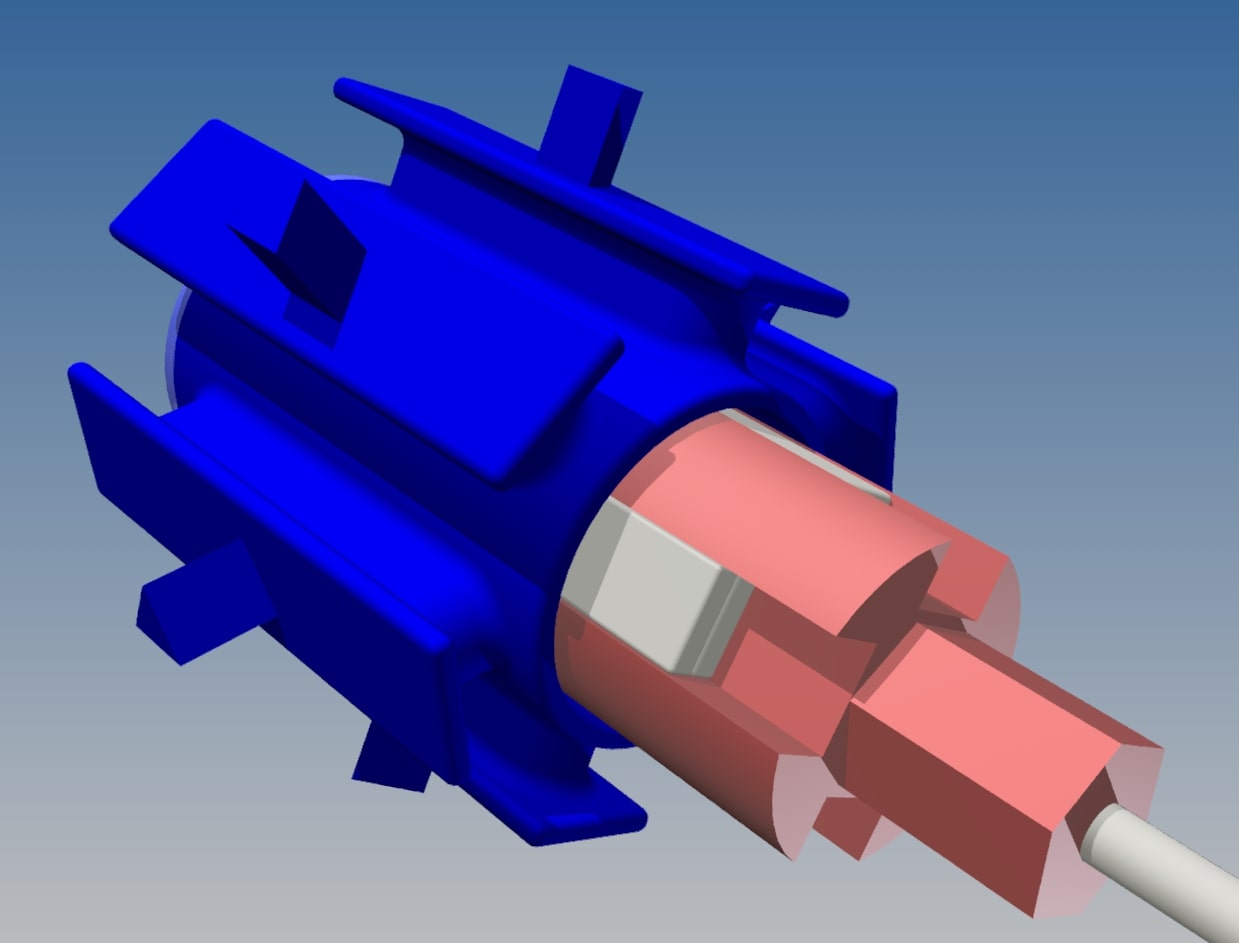
The second iteration has 12 poles for a three phase configuration. This would normally be a difficult change without the advantages of CAD modeling and 3D printing. Since the stator windings were designed as a single model arrayed about the motor axis, only one design parameter was changed to add an additional four poles. The final CAD model is displayed in Figure 1.
The rotor and stator were both printed upright on the FlashForge Finder 3D printer in PLA with 20% infill and standard resolution. Two prints took a total of 7 hours. However, the generator could theoretically be printed assembled in its final form to reduce printing time.
Once the Stator was finalized and printed, 26 AWG magnetic core wire was wound onto each pole. The poles symmetric to each other are wired in series with one continuous strand. Each phase of the stator was connected in a wye configuration. The entire winding process using an electric drill to spin the stator took only about 30 minutes to complete 600 total loops. Up front consideration of the manufacturing process proved successful in this generator's simple and intuitive assembly.
Initial testing was done using an electric corded drill connected to the stator shaft. Running the drill at 75% speed yields a phase voltage of roughly 8 volts at 60 Hz when connected to a three LED wye load. The open circuit test at the same frequency produces 10 volts peak-to-peak and the short circuit test yields approximately 0.589 amps. The synchronous reactance is estimated to be 17 Ω.
This design is not without its flaws. A proper mounting system was neglected in the early stages of design. Although winding the stator was simple, it required extreme precision to count each loop while keeping the wire from snagging on protruding features. A system such that the windings could be wound on a jig, removed, then installed on the stator would save time and effort.