December 4, 2020
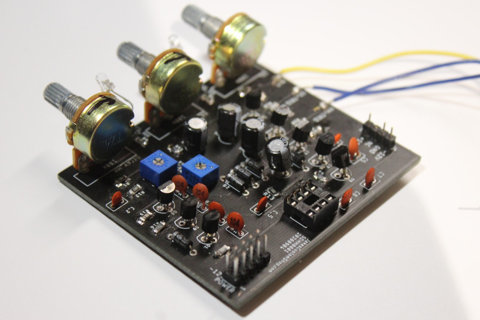
After a long two weeks of waiting for the Drum Machine PCB to arrive in the mail, I immediately got soldering. It took about three hours to assemble the first PCB among its many transistors, resistors, capacitors and potentiometers. Unfortunately there was an error in the input stage of the device. It appeared as thought the transistor amplifiers were being fried for an unknown reason.
I spent an enormous amount of time probing the PCB, replacing components and performing various tests. No success. In a last-ditch effort to confirm that my nearly complete 4-year engineering degree was not wasted; I rebuilt the entire circuit on a breadboard for the second time. Sure enough that worked just fine, but that didn't solve any underlying problems. I began building the Drum Machine again, this time on a fresh PCB. I worked in stages, testing successively. This fresh PCB-Drum Machine worked exactly how it should. Other than reducing the decay caps from 100 microfarads to 3.3 microfarads, the overall design remained intact.
Here’s a few notes I took along the way about PCB design.