August 8th, 2024
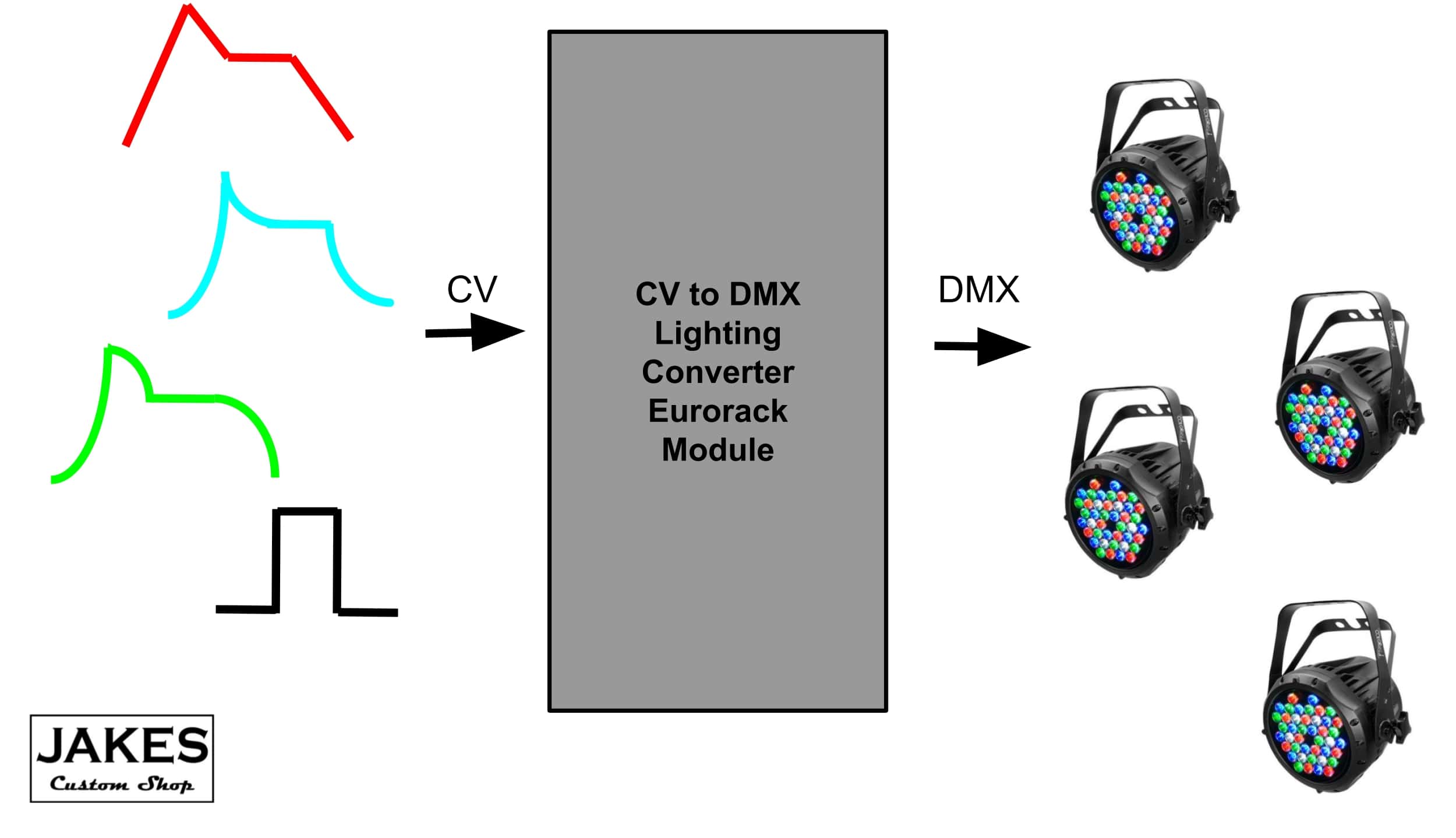
“A module that allows me to line in triggers or audio sources to a channel and then have that change act basically as a gate to turn various lights on and off. That way the lights aren't really tied to an sound spectrum but rather the parts/instruments I assign to each channel.”
A Control-Voltage to DMX converter eurorack module
...Is what Anthony described to me at Fire Lights Music festival this summer.

November 11th, 2024 - Layout Design
There are two ways I can take this
Option 1) Few inputs, Small HP, chainable
- Lower cost per unit, but vastly more expensive if users want to have more outputs
- Lower bar to entry with only a few CV inputs for a few lights, wider market.
- Smaller HP width → larger market
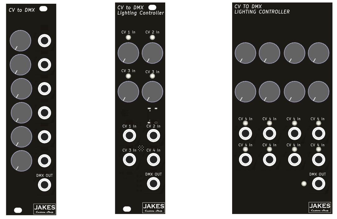
Designs 1,2, and 3 follow this idea with a minimal footprint but limited Functionality
Option 2) Many inputs, largeish HP, Skip the chainable SW
- Lower cost for many inputs
- Probably less work to design, no need for chaining.
- How many inputs are actually useful?
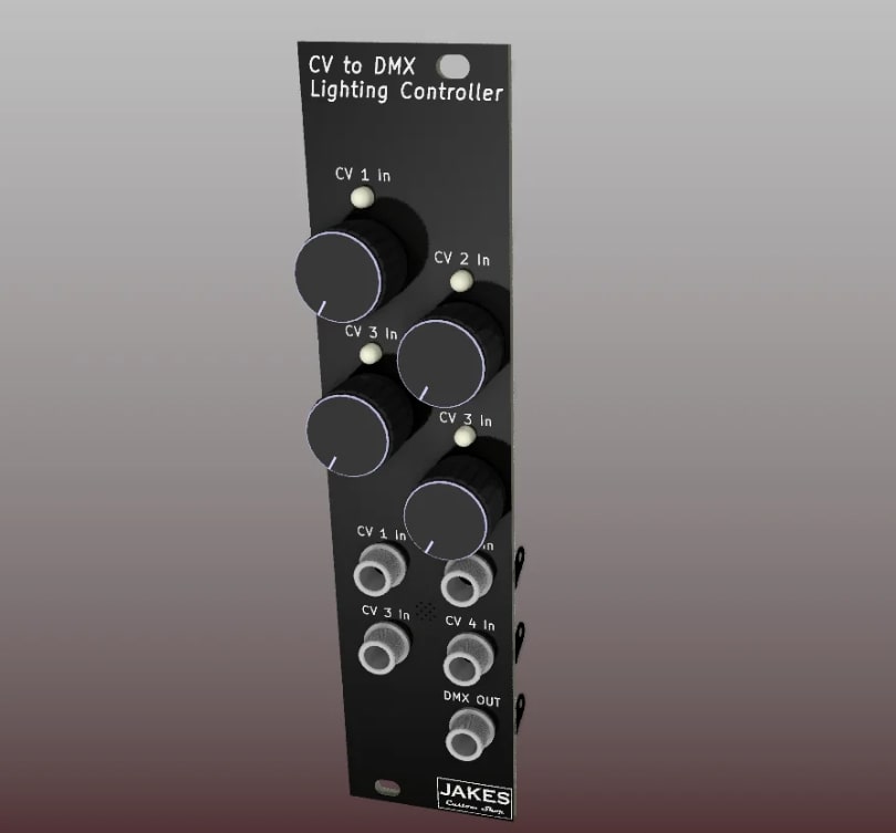
Design number 4 boasts 8 CV inputs that can alll be maped to a singel DMX Universe. The design is not very visually appealing, but that can be fixed.
I'd really like to try using an ESP32-S3. However this microcontroller is likely way overkill, and significantly more expensive than the tried and true AtMega328p. The ESP also takes up more real estate requiring external flash, and an additional 3.3V power regulator.
But, If I build my own confidence in ESP, then I have a MUCH faster, more powerful microcontroller for larger more complex projects. 20 ADCs! Using only 4 for the CV-DMX seems like a waste of power, especially if I want to make this module chainable.
November 23th, 2024 - ESP32-S3 Implmentation
Today I began implementing the code onto an ESP32-S3. Made a nice 3-channel proto board on the back of an old VCO front panel. The ESP reads the CV value and outputs some sort of digital data. The DMX light does not yet respond to the signals. Looking at my notes from 20241113, it seems I need to pull the TX line high. Will try this later tonight. I am guessing that my circuit is bad. The code compiled fine once I updated the platformio.ini configuration file.
November 24th, 2024
- Pulled the RX line high via a small resistor.
- Turns out the DMX A/B pins are NOT reversible. You must get this right ➡️ Make it adjustable on PCBs.
- May still need smoothing caps on input. Blinking Red light occasionally turns on green if I have the attenuator turned all the way up. This could also be due to an overflow error.
- I am also finding that a full 512 DMX slots takes just enough time to make audio-syncing feel a bit off-wack. Trimming it down to, say 16 slots perfects musical clock-to-light syncing for even the highest BPM
November 30th, 2024
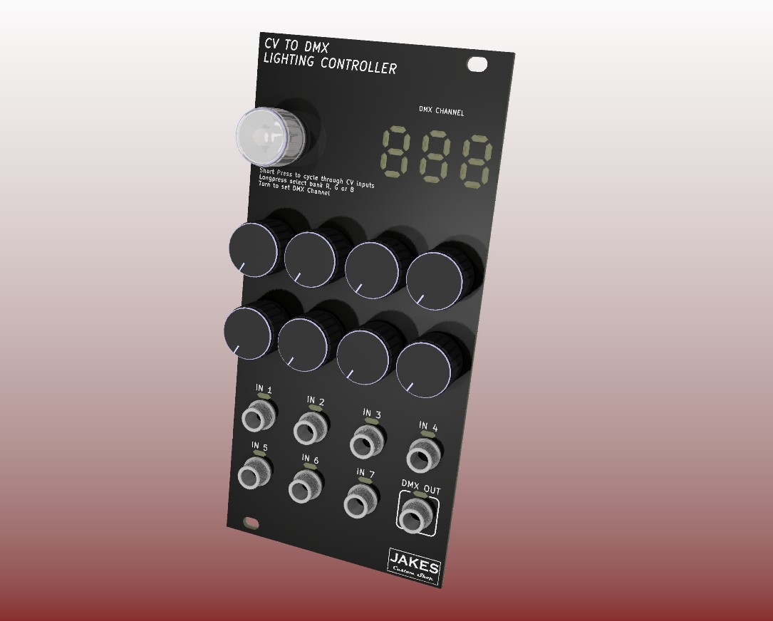
I'm thinking of adding a 3+ digit 7-segment display to the CV-DMX front panel using side-sticker LEDs diffused through the FR-4 PCB. Same concept as the Quad ADSR ring lights, but diffused, and displaying numerical values instead of rings. The Quad ADSR uses a MAX7219 LED Driver IC, which is designed for such applications. In fact, the C library I am using happens to have lookup tables for converting ASCII characters to LED values on the MAX7219.
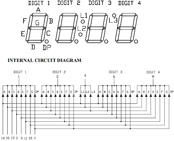
Setting the DMX channel will be done with a Rotary Encoder. Short press the RE knob to toggle between CV inputs, turn the knob to select DMX channel. It would also be cool to send 1 CV input to multiple DMX channels. That way a RGB light can flash or fade white by sending a single CV signal to a single CV input. OR you could sync multiple light fixtures to a single CV.
December 4th, 2024
Since the front panel has a built-in 7-Segment Display, I need to send signals from the main PCB to the front panel. On most of my past modules, I've used 2.54mm pin headers and sockets to make connections between PCBs. However the pin headers have two problems. 1. They are quite large 2. At least one pin header requires manual soldering since JLCPCB will only put components on one side of a PCB.
Enter the Flat Flexible Cable. These are the ultra thin, paper-like multi-conductors you see inside old computers and consumer electronics. The FFC connector takes up far less PCB space than a pin-header with the same number of conductors.
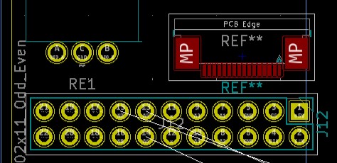
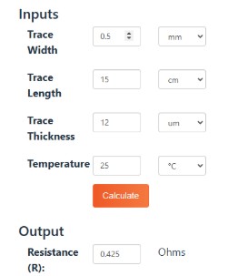
Since the FFC connector is so small (0.5mm pitch), I had to check that the it would be able to efficiently power the Eurorack Module's front panel LEDS. I used a free resistance calculator I found on Google. These are pretty easy to use. Input the Trace width, estimate the transmission length. Finding the Trace Thickness can be a bit harder. I used the standard value for flexible PCBs, 12 µm. Temperature is 25°C, standard room temp.
January 8th, 2025
Very close to being ready to launch. Created 2 ads promoting the CV-DMX Kickstarter to A/B test on both Reddit and Instagram. Also created a quick video to demo the module syncing LEDs to eurorack music. Marketing email is done.
January 9th, 2025 - Kickstarter launched!!! Wahoo!
(From the car)
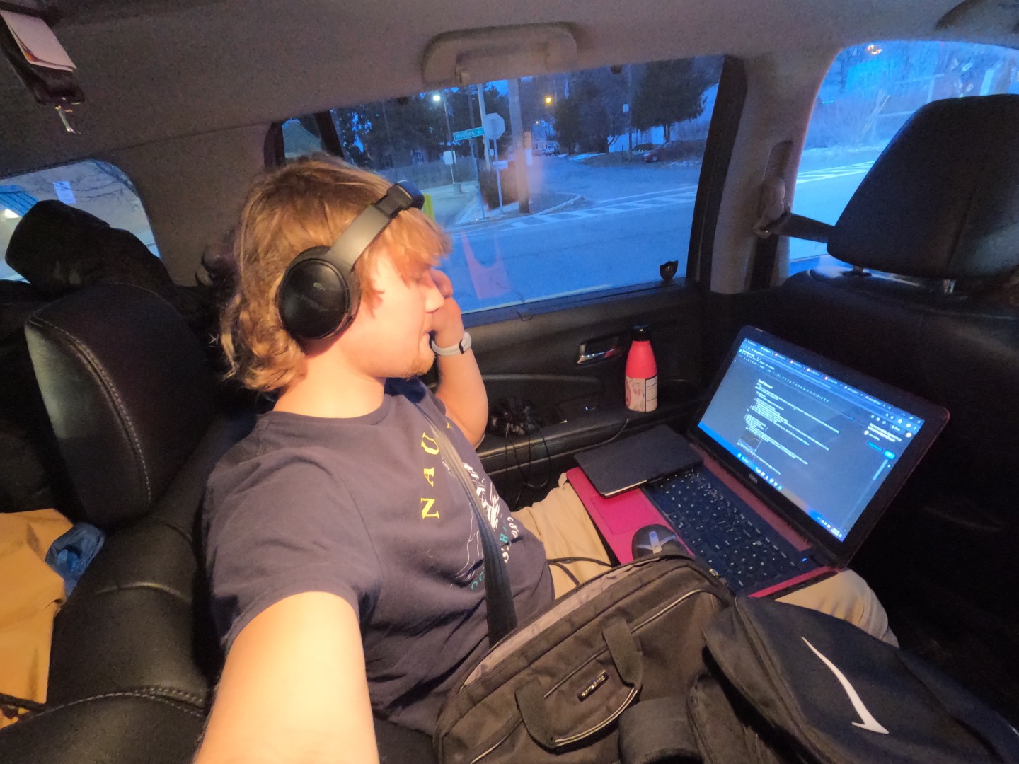
Today I opened up the Kickstarter Campaign for the CV-DMX Stage Light Controller module during the car ride home from Killington Vermont. Within 2 hours I have 3 Backers and 4 modules pre-ordered. This is a huge $ amount in a very short time, but in reality it's been 4 months... and a very focused past 7-days preparing. While my family was relaxing and having fun on a Vermont ski trip, I was producing two separate Instagram/ Facebook/ Reddit ads, a demo video, a marketing email, and 2 social media posts promoting the CV-DMX eurorack module. Can't forget the data sheet, infographics, 3D renderings, and webpage from the past month of work. Thien is hard at work on the main circuit PCB. The front panel, on my porch, awaits our arrival home.
Things done right so far
…and by 10pm, after only 4 hours we are 100 percent funded for a $1000 campaign. So grateful, so cool to be a designer of things people want😊😊
January 9th, 2025 - Front Panel Testing
Made a couple of quick scripts to test the front panel 7-segment displays. The display is not the easiest to read. Having some kind of weird issue where the display only counts to 20. When it gets to 20, the ESP resets.
January 12th, 2025 - PCBs and Kicker Start Half Way.
Wrote and sent the “CV-DMX-HalfWay” Email to my newsletter list, and posted an update to Kickstarter. Took ~1.5 hours. Also got the PCB V1.0, Stickers, and DMX cables in the mail yesterday.
Upon plugging in the first PCB into my PC, the Windows plug/ unplug jingle plays repeatedly. Concerning. Full Send, (the code), “Upload Complete ✓” and the Windows tone stops playing… did it work??!?!?!
Having an issue with the max485. I get the feeling that the pinout is incorrect but as many times i have checked, everything looks good. The datasheet says +12v is fine for Vcc, but the chip gets cooked instantly. 5v seems ok, but the DMX output is only 20mV peak to peak. There is a 22k pullup res to +12v, there are mixed documentation about its value. I’ve debugged issues with the RS485 three times now.
Output A is pulled high bia a 22kΩ resistor, I think it should only be pulled to +5V. This would bias the DMX signal to about 6V, which is now higher than the MAX485.
January 15th, 2025
A bit of PCB trickery and I am able to re-power the MAX485 with +5V. For V1.0 I am removing the resistor that pulls output-A high. This seems to fix the issue, and the CV-DMX works flawlessly!