May 10th, 2023
Design and assemble the necessary components and software to acquire .CSV data from a load cell during the release of pneumatically controlled elastomer mold.
Going into this project, there were a few different ways we could have achieved the requirements. Design option one was using an arduino as a DAQ. This is most similar to projects done in the past. However, there is no efficient way to save arduino serial data to .csv files aside from copy-pasting from the serial monitor. Option two was to use the Measurement Computing USB-231 DAQ device provided by the client. This is an analog input and output device that interfaces with a PC. Measurement Computing provides their own software and Python libraries. The included software worked fine, but lacked some key features such as load-cell calibration, automatic control of the solenoid air valve, and automatic .CSV file saving.
The final solutions involved using the MC USB-231 in combination with a Python Tkinter GUI, which runs through a Windows executable function generated by PyInstaller.
As we are exploring new software packages and custom hardware, we confirmed operations of each subsystem. The first and simplest sub-system test included calibrating the weight transmitter (to arbitrary values) and confirming operation of a load cell. The MC-231 DAQ could then be tested using the included software and a 4-20mA transmission from the amplifier.
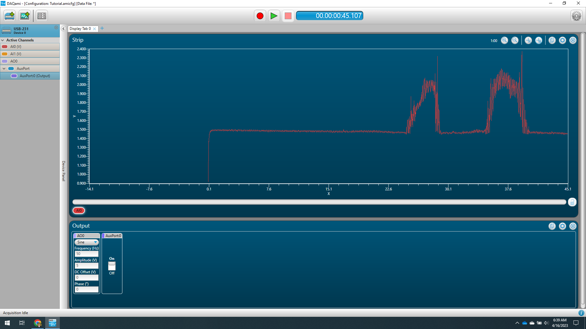
Now we could begin testing the python packages for data acquisition and building the graphical user interface. Measurement Computing provides example solutions for use with the USB-231 DAQ that outputs analog data directly to .CSV and can control the digital input/ output ports.
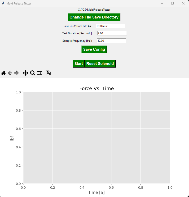
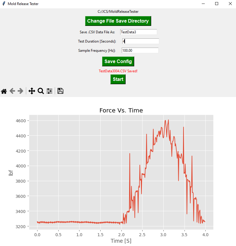
The Python package Tkinker is great for building simple interfaces. We used ChatGPT-3 to build the framework GUI then modified it to fit the Mold Release Tester design requirements. Figure 2 shows it collecting data from the load cell, saving it as a .CSV, and plotting the data. The operator has control over the automatic file save name and path (which increments for each sample), data collection duration, and sample frequency. A configuration file saves the setups for the next instance and another .csv holds the calibration data.
The initial design had the mold closing immediately after data was collected. Although convenient, this did not give the operator time to load the mold. So instead of automatically closing, the software interface now has a “reset mold” button that closes the mold when the operator is ready to test again.
Raw data from the load cell is a bit noisy, to smooth the data we added a rolling average for every 3 data points. Data is initially saved in units of volts which are converted to pound-force via a calibration function along with a .CSV datafile. The MRT software uses a first-order line of best-fit. This was found sufficient for our use case.
.jpg)
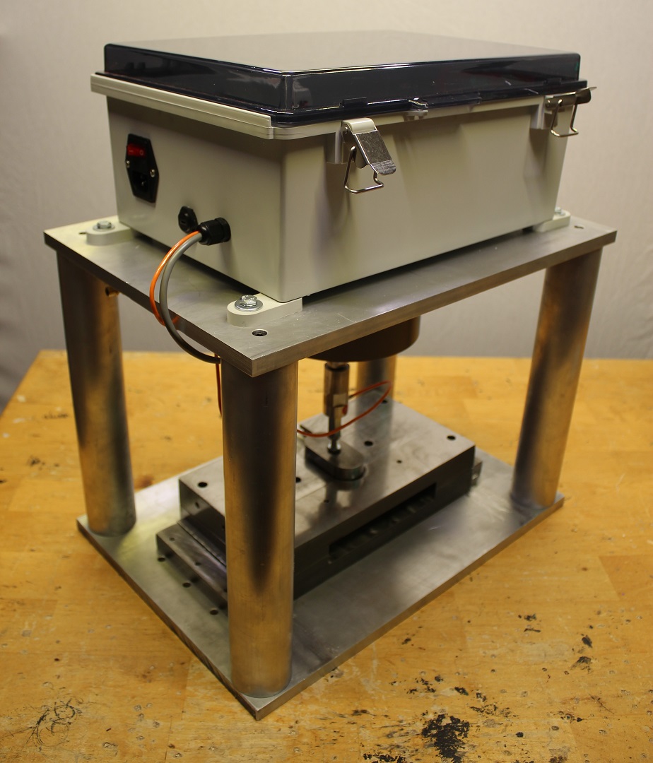
A weatherproof junction box conveniently houses all of the necessary electronics for a SCADA system. This consists of both AC and DC circuits for controlling the solenoid air valve, load cell amplifier and DAQ. AC power is connected to the box via a fused and switched IEC-C14 receptacle and serial data communicated to a PC via a standard USB-micro terminal. This setup is clean, simple and uses standard components to make repair and future modifications easy.
.jpg)
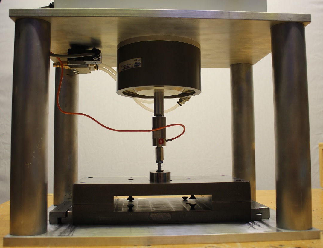
In order to control the actuation of the air cylinder, we implemented a 5-way solenoid air valve. When a high-signal is sent to the solenoid, the air cylinder retracts thus opening the mold. During this process, the software backend collects analog data from the load cell. The mold remains open until the operator is ready to reset the system.
A Graphical User Interface was developed using Python and Tkinter and runs directly from a windows executable file. The interface gives the user options to select a file directory, choose a file name, edit the sample duration and edit the sampling frequency. The “Save Config” button saves the user parameters between instances of the program. This ensures that testing sessions are consistent and repeatable. When the operator is ready to run a test, he or she simply clicks “Start.” The mold is pneumatically released after 0.5 seconds of data collection. After the prescribed test duration, recorded data is saved to a .CSV file, converted from volts to pounds, filtered, and plotted on the GUI. The cured rubber is then removed from the mold, and the system is reset by selecting the “Reset Solenoid” button. When the next sample is ready to be released, the user simply clicks “Start.” .CSV data file names are automatically incremented to prevent overwriting data. A complete suit of status messages indicate system state, invalid parameters, and data errors for debugging. Two levels of debugging are implemented into the python code for developers.