September 18th, 2023
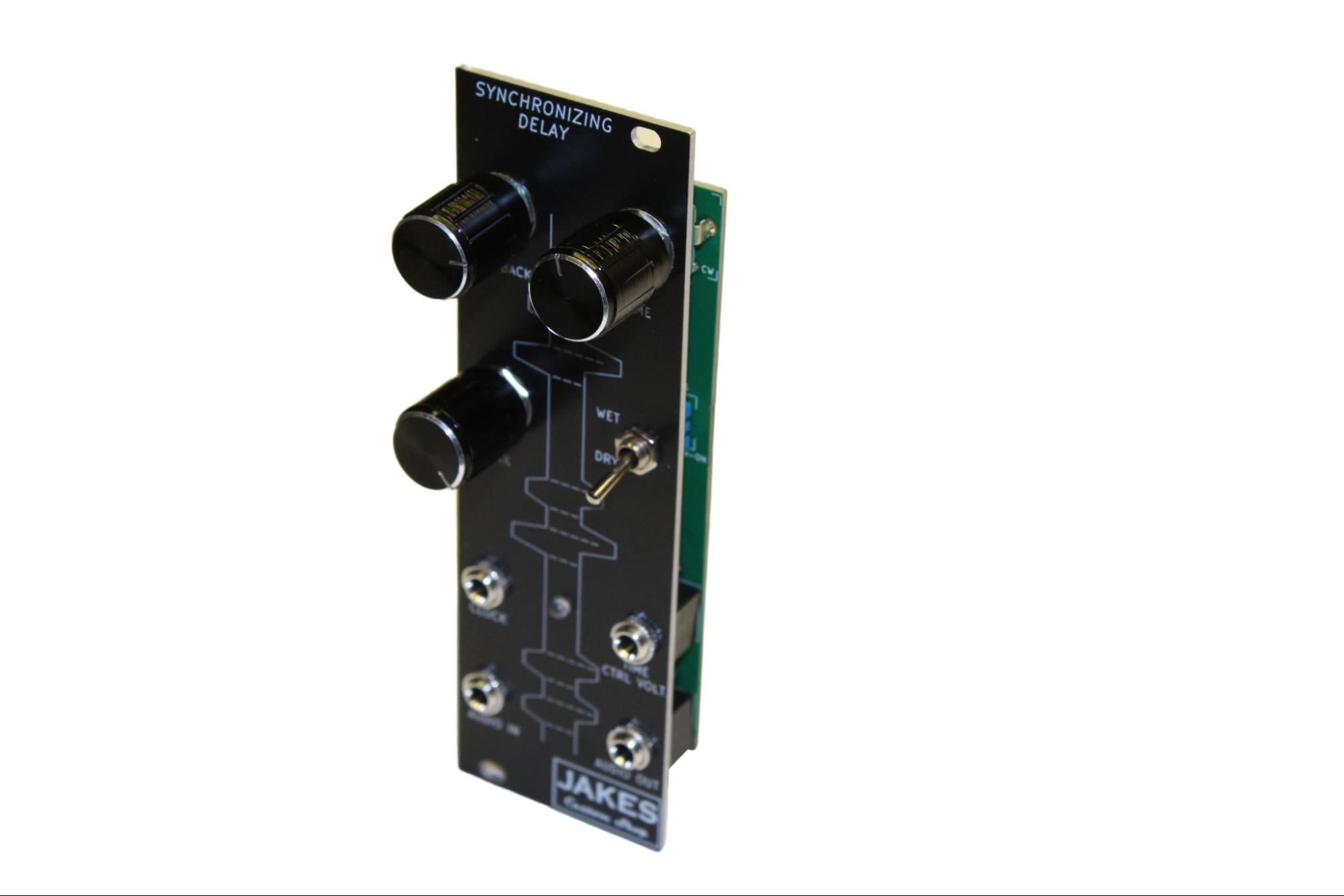
Up until this point, Jake's custom shop has only released analog eurorack modules. With a nearly complete masters degree in embedded software engineering, I’m looking for a new challenge. This leads us to the Synchronizing Delay Eurorack module. There are many PT2399 based delay modules. However, by implementing an AtMega328p microcontroller, we can greatly increase this device's functionality.
The PT2399 is a single-chip echo processor IC (integrated circuit) that uses CMOS (complementary metal-oxide semiconductor) technology. It was developed by Princeton Technology Corporation and was originally intended for use in karaoke machines and other audio entertainment systems. However, it has become increasingly popular in the DIY community due to its ability to emulate the sound of analog delay circuits. It features a high sample rate ADC/DAC, 55kb of RAM, built-in low-pass filtering and internal VCO. This minimizes the need for complex external circuitry.
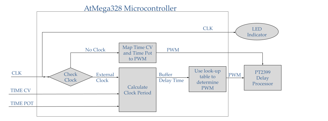
By utilizing a microcontroller to modulate the PT2399’s Frequency Adjustment Pin, delay time becomes software controlled. This is incredibly useful for syncing echoes to an external musical pattern or control voltage signal. Software was built in C to generate an appropriate PWM signal to achieve the desired delay time from the PT2399. This requires a 3rd-order curve interpolation according to the 3 inputs, Clock, Time CV, and the Time Potentiometer. The system defaults to Clock Synchronization mode, however if no clock is detected, the Time CV and Time Pot are used to determine the delay time.
A significant portion of design time was dedicated to ensuring that the on-board embedded system could be easily and efficiently flashed with custom software. Figure 2.a. shows the 6-Pin ISP header used to interface from an external programmer to the onboard system. A 2x3pin, 2.54mm pitch, through-hole header was used to allow for easy binding with a ISP pogo-pin clip. The pogo-pin clip clamps onto the PCB and accepts a standard IDC cable that is broken out to an Arduino Nano. A 16 MHz crystal oscillator was also implemented to ensure fast and stable operation.
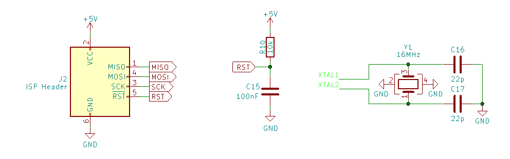
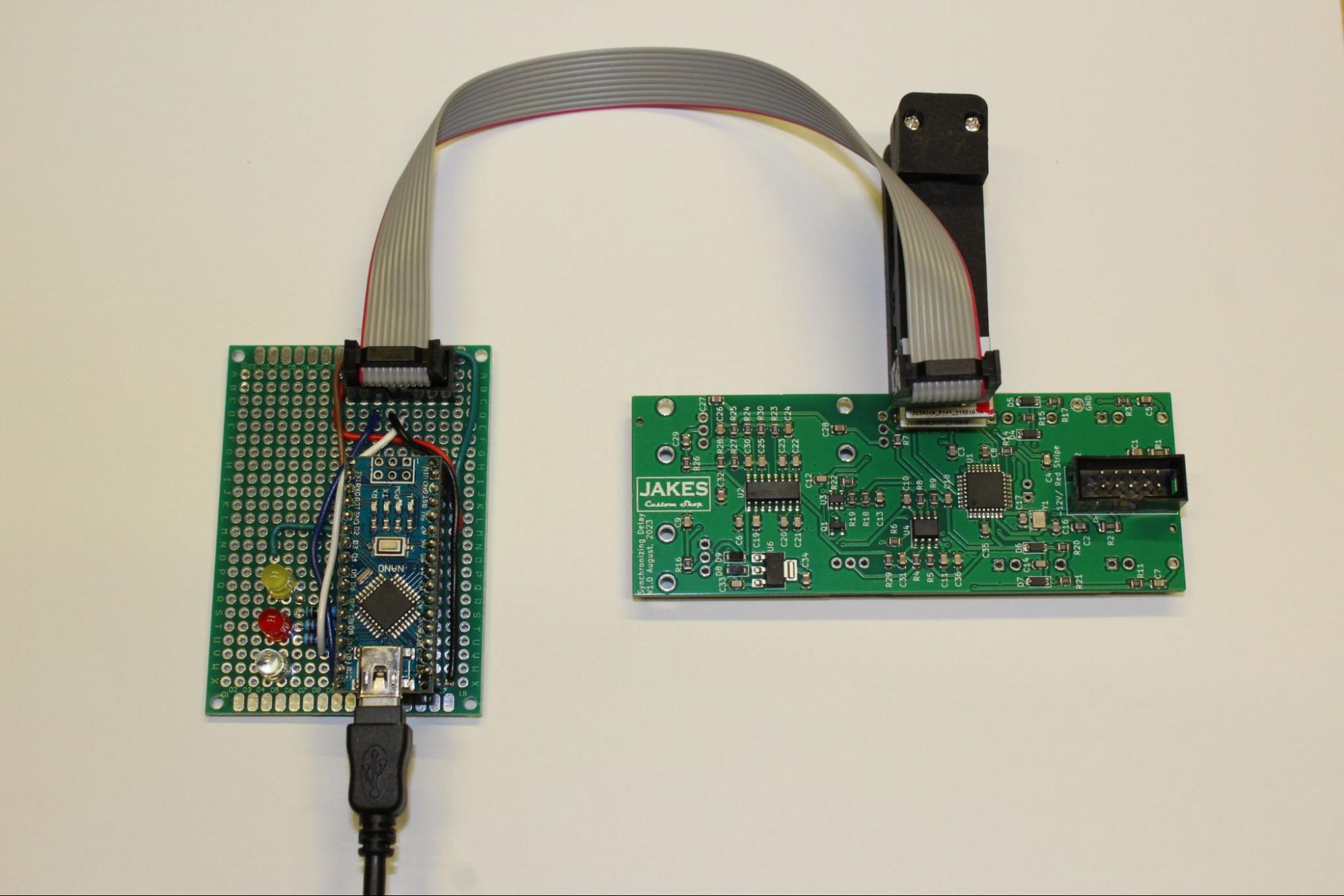
Figure 3 shows the purpose-built programer used for the Delay module. This consists of an Arduino Nano on a protoboard, 3 indicator LEDs, IDC cable, and a pogo-clip connector. This arrangement makes flashing of many chips simple, quick, and reduces the chance of error. The system can easily be re-used for future projects.
For a first ISP project, this one went surprisingly smooth and the module turned out pretty cool. I fully expect to make a few more digital modules using this method.